Your exercise answers are saved by the browser in local storage
associated with this webpage. You can use the buttons below
to load/save the answers on your system.
Save all answers:
Load all answers (this will overwrite any answers currently saved by the browser):
Authored by Chris Terman
Caches
When entering numeric values in the answer fields, you can use
integers (1000), floating-point numbers (1000.0), scientific notation
(1e3), engineering scale factors (1K), or numeric expressions (3*300 + 100).
Useful links:
Problem 1. Cache Architectures
Please read "Appendix: BSim Cache Simulation"
below to learn how to drive the cache simulator that's built into BSim.
We'll be using the following test program to explore the
behavior of caches:
.include "beta.uasm"

// A little cache benchmarking program: adds N words from
// array A, then repeats.  The starting addresses for the
// program and the array A are set by the I and A symbols
// below.

. = 0
  BR(test)        // branch to the start of the benchmark

I = 0x200        // location of benchmark program
A = 0x240        // starting address of array A
N = 16           // size of data region (in words)

. = I            // start benchmark program here
test:
  CMOVE(N,R0)    // initialize loop index J
  CMOVE(0,R1)

loop:            // add up elements in array
  SUBC(R0,1,R0)  // decrement index
  MULC(R0,4,R2)  // convert to byte offset
  LD(R2,A,R3)    // load value from A[J]
  ADDC(R3,0,R1)  // add to sum
  BNE(R0,loop)   // loop until all words are summed

  BR(test)       // perform test again!

// allocate space to hold array
. = A
  STORAGE(N)     // N words
This test program is pre-loaded into the BSim instance below.
Note that any changes you make to the program (e.g.,
changing symbol values) will not be saved when leaving the BSim window.
"cache_test.uasm" tab has a read-only version of the program
in case you need to copy it into the "Lab 6" to start with a clean
slate.
{ "initial_state": {
"beta.uasm": "url:../exercises/beta.uasm",
"cache_test.uasm": "url:../exercises/caches/cache_test.uasm"
},
"state":{"Cache test": "url:../exercises/caches//cache_test.uasm"}
}
Hint: In answering the questions below you may find it useful to
make changes to the assembly-language program to add .breakpoint,
run slightly different experiments, etc. Help yourself! You can
always restore the original program by closing the BSim window,
then reopening it.
Ideal Cache Behavior
Try assembling the program, opening the cache control, turning
on the cache, then clicking on the "Run Fast" control, which runs
the test in a continuous loop. You'll observe that with the
initial placement of the instructions and the array, and the initial
cache configuration, the cache hit ratio is essentially 1.00.
There are few compulsory misses (e.g., 9 IFetch
misses), i.e., misses that bring the instructions and data into
the initially empty cache. If the value of the symbol N were
temporarily changed from 16 to 8, what would the new miss numbers be?
The key to understanding cache performance is understanding how
the memory address received from the CPU is processed by the cache
hardware. Here's the right recipe:
Look at the assembly language program to determine
instruction and data addresses generated by the CPU as the
program executes. The sequence of addresses is sometimes called
the reference string.
Then look at the "Address bits" info in the cache
control panel to determine how each memory address is divided
into offset, index and tag fields. The index bits determine the
cache line and the tag bits of the address are compared with the
the tag field of the selected cache line to determine if there's
a hit.
Our cache has 64 data words altogether. The initial
configuration is direct mapped with 1 word/line, so the cache has
64 lines numbered 0 through 63. To achieve the 100% hit ratio, it
must be the case that the instructions and array data can reside
in the cache at the same time.
Please determine which cache line will hold each of the
following instruction or data words. And for practice, compute
the tag field for each of the addresses. Remember that to enter an
address in hex, you should include a 0x prefix.
Aha! All the instruction and data words map to different cache lines,
so all of instructions and data accessed by the loop can reside in
the cache at the same time.
Collisions
Now let's change the location of the A array in memory by modifying
the appropriate line in the assembly language program to be
A = 0x300 // starting address of array A
If you changed N to 8 for the previous question, please reset it
to 16. Rerun the simulation for a while with the cache enabled and observe that
the hit ratio on instruction fetch is now .904 and the overall hit ratio is
.838.
Determine which cache lines will now hold the A array and compute
the associated tag field.
Moving A means that addresses for A[0] through A[7] are mapped
into the same cache lines as those used for the instructions. The
data accesses to A and instruction fetches are said to collide, i.e.,
since their addresses map to the same cache lines, they contend for
residency in the direct-mapped cache.
The data for A[4] maps to the same cache line as which
instruction? Recall that A[0], the first element of the array
is located at address 0x300.
Why is the long-term instruction fetch hit ratio .904? Let's do
the calculations for one complete iteration of the outer
loop, which involves N (16) iterations of the inner loop. Consider
execution starting with the instruction at test: and ending
when the same instruction is about to be executed again.
Hint: placing a .breakpoint just after test: will let
you compare the cache statistics between two successive iterations
of the outer loop and use the difference to answer the questions
below. Or, of course, you can simply figure it out from the
assembly language program! We're interested in the steady
state behavior, so don't use measurements from the first iteration
of the loop, which would include cumpulsory misses when filling
the empty cache.
What is the total number of instruction fetches during
one full iteration of the outer loop?
The sixteen iterations of the inner loop access A[15] down to
A[0]. Recall that accesses to A[0] through A[7] collide with the
instructions. So some of those data access will end up replacing
an instruction in the cache, which will then cause a cache miss
when that instruction is fetched on the next iteration of the
inner loop.
What are total numbers of misses and hits for one full
iteration of the outer loop?
If we compute the hit ratio as hits/(total fetches) we
get 0.9036.
Associativity
Keeping the new address for the A array, change the
associativity setting from "direct mapped" to "2-way". Note that
the 64 total cache lines are now divided into two ways, each
having 32 lines. So the address bits used to select the cache
line are a bit different (pun intended!) than before. If you
added a .breakpoint, you can remove it now. Rerun the
simulation for a while and observe the new hit ratio: 1.00 again!
Why does the 2-way set-associative cache have a
better hit ratio on data accesses than the direct-mapped cache?
A[0] through A[7] and the instructions now map to
disjoint sets of cache lines and no longer collide. A[0] and CMOVE(N,R0) can both reside in
the cache at the same time (one in each of the two ways)
even though their addresses map to the same cache
line. And so on for the other collisions in the
direct-mapped cache. There's a bug in the cache simulation.
So far our experiements have involved only a few instructions and
data words which will all fit in the 64-word cache if we can arrange for
them not to collide either by appropriate choice of addressing or by
using a 2-way set-associative cache.
Now let's consider what happens when we access a much larger
array. Modify the assembly language program to be
A = 0x300        // starting address of array A
N = 64           // size of data region (words)
Run the modified program with the most recent cache settings: 64
total words, 1 word/line, 2-way associativity.
Report the hit ratio percentages for Ifetch and Dread:
You should be able to explain these results!
The very high Ifetch hit ratio is pretty easy to explain, using
the approach from parts (E) and (F). The instructions in the
inner loop are all executed once for each data access, so the
cache lines holding these instructions will never be "least
recently used" when a cache line needs to be replaced due to a
data miss. This means the instructions in the inner loop will always
be in one way of the cache after the initial instruction fetch.
So it's just the 2 instructions at the beginning of the outer loop
and the one at the end that generate the 3 misses for each
iteration of the outer loop. Running the numbers: total
instruction fetches = 64*5+3 = 323; total misses = 3; Ifetch hit
ratio = 320/323 = 0.9907.
To analyze the Dfetch hit ratio, it's helpful to refer to
the figure on the right, which sketches the layout of a 2-way
set-associative cache with 64 total words. The instructions occupy
lines 0-7 in one of the ways (shown conceptually as the shaded area
of the cache). That leaves the other 7/8 of the cache for holding
array data.
The 64 elements of the array collide with themselves in a
cache with 32 lines.
For example, A[17] collides with A[i]
for what value of i?
Since the cache is 2-way set-associative, two addresses
that collide can both reside in the cache. So 75% of the
array values (those that map to cache lines 8 through 31)
will stay in the cache once they're loaded. But 25%
of the array elements also collide with the instructions.
There are two array values, A[j] and A[k],
that collide with the instruction ADDC(R3,0,R1).
What are the values for j and k? Enter the
smaller of the two indicies as the value for j.
It's these 25% of the array elements that collide with
each other that lead to cache misses and refills from
one iteration of the outer loop to the next. Hence the .75
hit ratio for Dfetches.
Block size (words/cache line)
Finally, let's make one last adjustment to the cache controls:
change the words/line to the value 2, still keeping the address of
the array at 0x300. This changes the layout of
the cache once again: each of the 2 ways now has 16 cache lines,
but each cache line now holds 2 words of data. The first word in
a cache line will be from a memory location whose byte address is
a multiple of 8, the second word will be from the following memory
location. When a cache line is refilled both words are read
from memory and stored in the cache -- there's no notion of a
partially-filled cache line.
Suppose A[53] is resident in our cache as currently
configured (64 total words, 2 words/line, 2-way set-associative).
Looking at the assembly language program, determine
the memory address for A[53].
If A[53] is resident in the cache, A[m]
will also be present in the same cache line.
If A[53] is resident in the cache, in which
cache line will it reside? In other words, what's the value
of the index field of the address you entered above?
If A[53] is resident in the cache, what will
be the value of the tag field for that line?
Rerun the program for a while with the new cache configuration.
Report the hit ratio percentages for Dread:
Doubling the number of words/line has halved the number of
Dread misses in each iteration of the outer loop! Why? The
refill triggered by each miss brings in two entries from the array,
the one that's needed to satisfy the current LD instruction, and
the memory location that will be accessed by LD in the next
iteration of the inner loop. For example, if there's a miss when
loading A[7], both A[6] and A[7] are brought into the cache.
On the next iteration, the load of A[6] will be a hit! So every
second LD access is now a hit.
Moral of the story: sequential array accesses are good examples
of the principal of locality. An increased words/line will bring
in neighboring array elements on a miss and those neighbors will
be accessed in successive iterations. So at a slightly larger
refill cost (bringing in the extra words), there's a big impact
on the miss rate.
Problem 2. Design Problem: Set-associative Instruction Cache
See the instructions below.
Use the Jade instance below to enter your design. Your design
will be saved to the server each time you run a simulation.
{ "hierarchical": "true",
"parts": ["/gates/.*","/caches/.*","memory","/user/.*"],
"tools": ["check","timing"],
"editors": ["schematic","icon","test"],
"edit": "/caches/test",
"initial_state":
{
"/caches/test": {"test": [["test", ".power Vdd=1\n.thresholds Vol=0 Vil=0.1 Vih=0.9 Voh=1\n\n.group inputs reset ia[31:0]\n.group outputs irdy id[31:0]\n\n.mode gate\n\n.cycle CLK=1 tran 10n assert inputs tran 40n CLK=0 tran 49n sample outputs tran 1n\n\n1 -------------------------------- - -------------------------------- // 1 reset\n\n// read 0x000. It's a miss, so fetch the 2-word block at locns 0 and 4 from main memory\n// way 0 is LRU, so put the data there in line 0. then make way 1 LRU for cache line 0.\n0 00000000000000000000000000000000 L -------------------------------- // 2 read locn 0 => miss\n0 00000000000000000000000000000000 L -------------------------------- // 3 read locn 0 RD1\n0 00000000000000000000000000000000 H LLLLLLLLLLLLLLLLLLLLLLLLLLLLLLLL // 4 read locn 0 RD2 => done\n\n// read 0x004 Expect a hit in line 0, way 0.\n0 00000000000000000000000000000100 H LLLLLLLLLLLLLLLLLLLLLLLLLLLLLLLH // 5 read locn 4 => hit\n\n// read 0x100 (which also maps to cache line 0) => a miss, but fill line 0 in way 1\n// way 0 now becomes LRU for cache line 0\n0 00000000000000000000000100000000 L -------------------------------- // 6 read locn 100 => miss\n0 00000000000000000000000100000000 L -------------------------------- // 7 read locn 100 RD1\n0 00000000000000000000000100000000 H LLLLLLLLLLLLLLLLLLLLLLLLLHLLLLLL // 8 read locn 100 RD2 => done\n\n// read 0x004. Should still be a hit in line 0, way 0.\n0 00000000000000000000000000000100 H LLLLLLLLLLLLLLLLLLLLLLLLLLLLLLLH // 9 read locn 4 => hit\n\n// read 0x104. Expect a hit in line 0, way 1.\n0 00000000000000000000000100000100 H LLLLLLLLLLLLLLLLLLLLLLLLLHLLLLLH // 10 read locn 104 => hit\n\n// read 0x204. Expect a miss; refill line 0, way 0; way 1 becomes LRU\n0 00000000000000000000001000000100 L -------------------------------- // 11 read locn 204 => miss\n0 00000000000000000000001000000100 L -------------------------------- // 12 read locn 204 RD1\n0 00000000000000000000001000000100 H LLLLLLLLLLLLLLLLLLLLLLLLHLLLLLLH // 13 read locn 204 RD2 => done\n\n// read 0x104. Expect a hit since it should still be in line 0, way 1.\n0 00000000000000000000000100000100 H LLLLLLLLLLLLLLLLLLLLLLLLLHLLLLLH // 14 read locn 104 => hit\n\n// read 0x3FC => a miss, fill line 31, way 0\n0 00000000000000000000001111111100 L -------------------------------- // 15 read locn 3FC => miss\n0 00000000000000000000001111111100 L -------------------------------- // 16 read locn 3FC RD1\n0 00000000000000000000001111111100 H LLLLLLLLLLLLLLLLLLLLLLLLHHHHHHHH // 17 read locn 3FC RD2 => done\n\n// read 0x100. Expect a hit in line 0, way 1\n0 00000000000000000000000100000000 H LLLLLLLLLLLLLLLLLLLLLLLLLHLLLLLL // 18 read locn 100 => hit\n// read 0x200. Expect a hit in line 0, way 0\n0 00000000000000000000001000000000 H LLLLLLLLLLLLLLLLLLLLLLLLHLLLLLLL // 19 read locn 200 => hit\n// read 0x3F8. Expect a hit in line 31, way 0\n0 00000000000000000000001111111000 H LLLLLLLLLLLLLLLLLLLLLLLLHHHHHHHL // 20 read locn 3F8 => done\n\n\n.plot clk\n.plot reset\n.plot X(ia[31:0])\n.plot irdy\n.plot X(id[31:0])\n.plot X(xma[31:3])\n.plot X(xdata[63:32])\n.plot X(xdata[31:0])\n\n\n"]], "properties": {"icon-readonly":"true","test-readonly":"true","schematic-readonly":"true","name": {"edit": "yes", "type": "name", "value": "", "label": "Name"}}, "schematic": [["memory", [80, -40, 0], {"ndata": "64", "name": "Main", "naddr": "9", "contents": "0x0000000100000000\n0x0000000300000002\n0x0000000500000004\n0x0000000700000006\n0x0000000900000008\n0x0000000B0000000A\n0x0000000D0000000C\n0x0000000F0000000E\n\n0x0000001100000010\n0x0000001300000012\n0x0000001500000014\n0x0000001700000016\n0x0000001900000018\n0x0000001B0000001A\n0x0000001D0000001C\n0x0000001F0000001E\n\n0x0000002100000020\n0x0000002300000022\n0x0000002500000024\n0x0000002700000026\n0x0000002900000028\n0x0000002B0000002A\n0x0000002D0000002C\n0x0000002F0000002E\n\n0x0000003100000030\n0x0000003300000032\n0x0000003500000034\n0x0000003700000036\n0x0000003900000038\n0x0000003B0000003A\n0x0000003D0000003C\n0x0000003F0000003E\n\n0x0000004100000040\n0x0000004300000042\n0x0000004500000044\n0x0000004700000046\n0x0000004900000048\n0x0000004B0000004A\n0x0000004D0000004C\n0x0000004F0000004E\n\n0x0000005100000050\n0x0000005300000052\n0x0000005500000054\n0x0000005700000056\n0x0000005900000058\n0x0000005B0000005A\n0x0000005D0000005C\n0x0000005F0000005E\n\n0x0000006100000060\n0x0000006300000062\n0x0000006500000064\n0x0000006700000066\n0x0000006900000068\n0x0000006B0000006A\n0x0000006D0000006C\n0x0000006F0000006E\n\n0x0000007100000070\n0x0000007300000072\n0x0000007500000074\n0x0000007700000076\n0x0000007900000078\n0x0000007B0000007A\n0x0000007D0000007C\n0x0000007F0000007E\n\n0x0000008100000080\n0x0000008300000082\n0x0000008500000084\n0x0000008700000086\n0x0000008900000088\n0x0000008B0000008A\n0x0000008D0000008C\n0x0000008F0000008E\n\n0x0000009100000090\n0x0000009300000092\n0x0000009500000094\n0x0000009700000096\n0x0000009900000098\n0x0000009B0000009A\n0x0000009D0000009C\n0x0000009F0000009E\n\n0x000000A1000000A0\n0x000000A3000000A2\n0x000000A5000000A4\n0x000000A7000000A6\n0x000000A9000000A8\n0x000000AB000000AA\n0x000000AD000000AC\n0x000000AF000000AE\n\n0x000000B1000000B0\n0x000000B3000000B2\n0x000000B5000000B4\n0x000000B7000000B6\n0x000000B9000000B8\n0x000000BB000000BA\n0x000000BD000000BC\n0x000000BF000000BE\n\n0x000000C1000000C0\n0x000000C3000000C2\n0x000000C5000000C4\n0x000000C7000000C6\n0x000000C9000000C8\n0x000000CB000000CA\n0x000000CD000000CC\n0x000000CF000000CE\n\n0x000000D1000000D0\n0x000000D3000000D2\n0x000000D5000000D4\n0x000000D7000000D6\n0x000000D9000000D8\n0x000000DB000000DA\n0x000000DD000000DC\n0x000000DF000000DE\n\n0x000000E1000000E0\n0x000000E3000000E2\n0x000000E5000000E4\n0x000000E7000000E6\n0x000000E9000000E8\n0x000000EB000000EA\n0x000000ED000000EC\n0x000000EF000000EE\n\n0x000000F1000000F0\n0x000000F3000000F2\n0x000000F5000000F4\n0x000000F7000000F6\n0x000000F9000000F8\n0x000000FB000000FA\n0x000000FD000000FC\n0x000000FF000000FE"}], ["wire", [80, -40, 0, -8, 0], {"signal": "xma[11:3]"}], ["wire", [80, -32, 0, -8, 0], {"signal": "1'1"}], ["wire", [80, -24, 0, -8, 0], {"signal": "0'1"}], ["wire", [80, -16, 0, -8, 0], {"signal": "0'1"}], ["wire", [152, -40, 0, 8, 0], {"signal": "xdata[63:0]"}], ["wire", [-16, -56, 0, 8, 0], {"signal": "xdata[63:0]"}], ["wire", [-16, -72, 0, 8, 0], {"signal": "xma[31:3]"}], ["wire", [-128, -16, 0, -8, 0], {"signal": "reset"}], ["wire", [-128, 0, 0, -8, 0], {"signal": "clk"}], ["/caches/icache", [-40, 48, 0], {"name": "icache"}], ["wire", [-128, -72, 0, -8, 0], {"signal": "irdy"}], ["wire", [-128, -56, 0, -8, 0], {"signal": "id[31:0]"}], ["wire", [-128, -32, 0, -8, 0], {"signal": "ia[31:0]"}]]},
"/caches/equal24": {"test": [["test", ""]], "properties": {"icon-readonly":"true","schematic-readonly":"true","name": {"edit": "yes", "type": "name", "value": "", "label": "Name"}}, "schematic": [["port", [-80, -128, 0], {"signal": "A[23:0]"}], ["port", [-80, -112, 0], {"signal": "B[23:0]"}], ["wire", [-32, -120, 0, 8, 0], {"signal": "eq[23:0]"}], ["wire", [-80, -48, 0, -8, 0], {"signal": "eq[5:0]"}], ["wire", [-80, -64, 0, -8, 0], {"signal": "eq[11:6]"}], ["wire", [-80, -80, 0, -8, 0], {"signal": "eq[17:12]"}], ["wire", [-80, -96, 0, -8, 0], {"signal": "eq[23:18]"}], ["wire", [-32, -72, 0, 8, 0], {"signal": "mx[5:0]"}], ["/gates/nand4", [-80, -96, 0]], ["/gates/xnor2", [-80, -128, 0]], ["wire", [-80, 0, 0, -8, 0], {"signal": "mx[1:0]"}], ["wire", [-80, -16, 0, -8, 0], {"signal": "mx[3:2]"}], ["wire", [-80, -32, 0, -8, 0], {"signal": "mx[5:4]"}], ["/gates/nor3", [-80, -32, 0]], ["wire", [-32, -16, 0, 8, 0], {"signal": "my[1:0]"}], ["/gates/nand2", [-80, 16, 0]], ["wire", [-80, 16, 0, -8, 0], {"signal": "my[1]"}], ["wire", [-80, 32, 0, -8, 0], {"signal": "my[0]"}], ["/gates/inverter", [-32, 24, 0]], ["port", [0, 24, 4], {"signal": "equal", "direction": "out"}]], "icon": [["terminal", [-40, -16, 0], {"name": "A[23:0]"}], ["terminal", [-40, 0, 0], {"name": "B[23:0]"}], ["terminal", [24, -8, 4], {"name": "equal"}], ["text", [-30, -16, 0], {"text": "A"}], ["text", [-30, 0, 0], {"text": "B"}], ["text", [14, -8, 0], {"text": "equal", "align": "center-right"}], ["text", [-8, -26, 0], {"text": "equal24", "align": "center", "font": "8pt bold sans-serif"}], ["line", [-32, -32, 0, 0, 40]], ["line", [-32, 8, 0, 48, 0]], ["line", [16, 8, 0, 0, -40]], ["line", [16, -32, 0, -48, 0]]]},
"/caches/icache": {"test": [["test", ""]], "properties": {"icon-readonly":"true","name": {"edit": "yes", "type": "name", "value": "", "label": "Name"}}, "schematic": [["port", [-184, -184, 0], {"signal": "ia[31:0]"}], ["port", [-184, -168, 0], {"signal": "reset"}], ["port", [-184, -152, 0], {"signal": "clk"}], ["port", [-216, -40, 4], {"signal": "xdata[63:0]", "direction": "in"}], ["port", [-184, -216, 0], {"signal": "irdy", "direction": "out"}], ["text", [-223, -229, 0], {"text": "CPU interface"}], ["text", [-236, -74, 0], {"text": "Main memory interface"}], ["jumper", [-224, -56, 0]], ["wire", [-224, -56, 0, -8, 0], {"signal": "ia[31:3]"}], ["port", [-216, -56, 4], {"signal": "xma[31:3]", "direction": "out"}], ["port", [-184, -200, 0], {"signal": "id[31:0]", "direction": "out"}], ["jumper", [-200, -112, 0]], ["wire", [-192, -112, 0, 8, 0], {"signal": "line[4:0]"}], ["wire", [-200, -112, 0, -8, 0], {"signal": "ia[7:3]"}], ["jumper", [-200, -128, 0]], ["wire", [-192, -128, 0, 8, 0], {"signal": "offset"}], ["wire", [-200, -128, 0, -8, 0], {"signal": "ia[2]"}], ["jumper", [-200, -96, 0]], ["wire", [-192, -96, 0, 8, 0], {"signal": "atag[23:0]"}], ["wire", [-200, -96, 0, -8, 0], {"signal": "ia[31:8]"}]], "icon": [["terminal", [-88, -80, 0], {"name": "ia[31:0]"}], ["terminal", [-88, -64, 0], {"name": "reset"}], ["terminal", [-88, -48, 0], {"name": "clk"}], ["terminal", [-88, -120, 6], {"name": "irdy"}], ["terminal", [24, -120, 2], {"name": "xma[31:3]"}], ["terminal", [24, -104, 2], {"name": "xdata[63:0]"}], ["terminal", [-88, -104, 6], {"name": "id[31:0]"}], ["text", [-78, -80, 0], {"text": "ia[31:0]"}], ["text", [-78, -64, 0], {"text": "reset"}], ["text", [-78, -48, 0], {"text": "clk"}], ["text", [-78, -120, 0], {"text": "irdy"}], ["text", [-78, -104, 0], {"text": "id[31:0]"}], ["text", [14, -120, 4], {"text": "xma[31:3]"}], ["text", [14, -104, 4], {"text": "xdata[63:0]"}], ["text", [-32, -134, 0], {"text": "ICACHE", "align": "center", "font": "10pt bold sans-serif"}], ["line", [-80, -40, 0, 96, 0]], ["line", [16, -144, 0, -96, 0]], ["line", [-80, -144, 0, 0, 104]], ["line", [16, -144, 0, 0, 104]]]}
}
}
Instructions
In this lab, you'll design a 2-way set-associative instruction
cache with a block size of 2 and an LRU replacement strategy.
Most modern CPUs use separate caches for instruction fetch and
data accesses as the first level of their memory hierarchy. That
way misses from data accesses will never interfere with cached
instructions, potentially increasing the hit rate of the
instruction cache. Instruction caches can be simpler since they
don't have to deal with write requests and so don't need the
machinery associated with dirty bits, write back, etc.
We'll test your design using the /caches/test module:
On the right of the diagram is the 64-bit wide main memory --
we're only showing the one port used for reading instructions.
This memory takes two clock cycles to complete a read operation.
The 64-bit width is a perfect match for the 2-word block size, i.e.,
a single access to main memory can refill an entire line of cache.
You'll be designing the component on the left, highlighted in
red. On its left are the interface signals that connect to the
instruction address (ia[31:0]) and instruction data
(id[31:0]). There's one additional signal, irdy, that
the cache generates to tell the Beta that the cache has completed the
requested instruction fetch during the current clock period. If
there's a cache hit, the request is completed in the cycle it is
issued. Otherwise, it will take two additional cycles before the request
is complete since the cache will have to access the slower main
memory.
These signals are described in detail in the final section
of this document.
You'll be entering your cache circuitry in the schematic for
the /caches/icache module. To test your design, use
the /caches/test module.
Cache memory
Each way of our 2-way set-associative cache will contain 32
cache lines and each cache line holds 2 data words. So to complete
a cache access, the incoming instruction address is divided up
as follows:
ia[1:0]
byte offset (ignored by cache)
ia[2]
word offset (selects word from 2-word cache line)
ia[7:3]
5-bit cache line index (selects cache line)
ia[31:8]
24-bit address tag field
Each cache line requires the following storage:
valid
1-bit flag is 1 if cache line is valid
tag[23:0]
24-bit tag field for this cache line
cdata[63:0]
64 bits (2 words) of data
which is a total of 89 bits. So each way requires its own 2-port
32x89 memory. One port is used for reading out the valid/tag/data
information for the requested cache line, and the other port is used
to write valid/tag/data information when a cache line is refilled.
So you'll need to add something like the following to the icache
schematic:
To initialize the valid bits for each line to 0, the initial
contents for each location should be specified as 0. To do this,
edit the memory's contents property and enter 32 lines of 0.
Of course, you'll have two of these with the appropriate changes to signal
names to keep the valid/tag/data info separate. xdata[63:0]
is the 64-bit data coming back from main memory during a refill
operation. The write enable signal (cwe0) is discussed in
the next section.
Cache control logic
On each cycle, the cache reads the line requested by the cache
line index field of the instruction address and then checks to see
if there's a cache hit by comparing the tag fields of the cache line
and instruction address:
We get a cache hit if the tags match, the cache line is
valid and (so we deal with start up correctly) if the reset signal
is 0. Here we've used the handy /caches/equal24 module
that compares two 24-bit values and tells us if they're equal.
Again, you'll need a copy of this logic for each way.
So now we know if a request has hit in either of the ways.
The next step is to deal with misses and generate the irdy
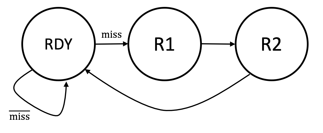
when the instruction data is ready to go. We can use a 3-state
FSM to control the cache operation:
Initially the FSM starts in the RDY state, waiting for requests
from the Beta. The following definitions will be useful in understanding
how the FSM works:
a request is a hit if in one of the ways the
selected cache line is valid, the address tag field matches
the cache line's tag field, and reset = 0.
a request is a miss if neither way reported a hit:
$\textrm{miss}= \overline{\textrm{reset}} \cdot \overline{\textrm{hit0}} \cdot \overline{\textrm{hit1}}$.
Here's how the FSM controls the cache to handle requests. Note that
the control signals for each state are summarized in a table below.
hit. If the request is a hit, it can be satisfied
by using ia[2] to select between CDATAx[31:0]
or CDATAx[63:32] to supply the value
of id[31:0] where "x" is the index of the way that
reported the hit. irdy can immediately be set to 1 and
the request is completed in the same cycle it was issued. The FSM
state remains at RDY.
miss. The correct cache line
contents must be filled from main memory and placed in whichever
way is least recently used. This is accomplished
in two clock cycles via FSM states R1 and R2.
The selected way is updated from xdata[63:0] at the end of
the R2 cycle. At the same time as we're updating the
cache line we can use ia[2] to select between
XDATA[31:0] or XDATA[63:32] to supply the value of
id[31:0]. Since we're completing the request, irdy
is set to 1 during the R2 cycle.
Using our usual ROM+reg FSM implementation, you might design something
like:
When editing the contents property of the ROM, remember that you need
to indicate the radix for each number you enter. 101 is the number
one hundred and one, 0b101 is the number 5. For ROMs used as
FSM controllers, you'll almost always want to use the 0b prefix.
The irdy and cwe outputs are determined by the
miss signal and the current state:
RDY
R1
R2
irdy
$\overline{\textrm{miss}}$
0
1
cwe
0
0
1
The cwe signal is combined with the LRU state (see below) to
generate the write enables for the two ways (cwe0 and cwe1).
So a request takes either 1 cycle to complete if it's a hit or
3 cycles to complete if it's a miss. Here's a table showing
where id[31:0] comes from
ia[2] = 0
ia[2] = 1
hit0 = 1
cdata0[31:0]
cdata0[63:32]
hit1 = 1
cdata1[31:0]
cdata1[63:32]
state = R2
xdata[31:0]
xdata[63:32]
LRU replacement strategy
The final piece of the puzzle is figuring out which way to
replace when there's a miss and we're reading the required data
from main memory. For a 2-way set-associative cache, we only need
one bit of state for each cache line. If the state bit is 0, then
way 0 holds the LRU cache line. If the state bit is 1, then way 1
holds the LRU cache line. Once we know which way is LRU, it's
easy to generate the correct write enable (cwe0
or cwe1) for the ways:
To initialize the LRU bits for each line to 0, the initial
contents for each location of the LRU state memory should be
specified as 0. To do this, edit the memory's contents property and
enter 32 lines of 0.
The LRU state needs to be updated at the end of every
request, i.e., whenever irdy is 1. If there was a hit
in way 0, or if we're updating way 0 during a refill, then
we set the LRU state bit to 1, indicating that way 1 now holds the
LRU cache line. In other words, if we just finished accessing
way 0 to complete the request, it's now the most recently used
cache line! And vice versa.
Testing
To test your icache design, switch to the /caches/test
module, click the green checkmark, and hope for the best!
Here's a rundown of the requests made:
read from location 0x000. This should be a miss since all
cache lines are invalid after reset. So the FSM should cycle
through states R1 and R2, filling line 0 of way 0 (the LRU way)
with the data from main memory. xdata[31:0] should
also be routed to id[31:0] and irdy set to 1
during the R2 cycle.
For cache line 0, way 1 is now LRU.
read from location 0x004. This should be a hit in line
0, way 0. irdy should be set to 1 in the cycle the request is
issued and cdata0[63:32] should be routed to id[31:0].
For cache line 0, way 1 is now LRU.
read from location 0x100. This location also maps to line
0 and should be a miss. But this time it's line 0 of way 1 that
gets refilled. For cache line 0, way 0 is now LRU.
read from location 0x004. This should be a hit in line
0, way 0. For cache line 0, way 1 is now LRU.
read from location 0x104. This should be a hit in line
0, way 1.
For cache line 0, way 0 is now LRU.
read from location 0x204. This should be a miss; replace
line 0, way 0.
For cache line 0, way 1 is now LRU.
read from location 0x104. This should be a hit in line
0, way 1.
For cache line 0, way 0 is now LRU.
read from location 0x3FC. This should be a miss; replace
line 31, way 0.
For cache line 31, way 1 is now LRU.
read from location 0x100. This should be a hit in line
0, way 1.
For cache line 0, way 0 is now LRU.
read from location 0x200. This should be a hit in line
0, way 0.
For cache line 0, way 1 is now LRU.
read from location 0x3F8. This should be a hit in
line 31, way 0.
For cache line 31, way 1 is now LRU.
Good luck!
Description of cache input/output signals
Here's a table describing the interface signals that connect
to the Beta's memory interface.
clk
input
clock (from test circuitry): a 10MHz square wave creating a 100ns
clock period.
reset
input
reset (from test circuitry): set by the test circuitry to 1 until
after the first rising edge of clk, then set to 0 to start
the cache running.
ia[31:0]
inputs
instruction address (from test circuitry): address of the instruction location in main
memory to be read. These signals are required to be stable and valid each cycle
since the cache assumes that the CPU is trying to fetch an instruction every
cycle.
id[31:0]
outputs
memory read data (from cache): the
cache will drive these signals with the contents of the
memory location specified by ia[31:0]. Only valid
during the cycle in which the cache sets irdy to 1.
irdy
output
instruction data ready (from cache): the cache sets this signal to indicate that
during this cycle id[31:0] is the instruction data read from
location ia[31:0].
And here's a table describing the interface signals that connect
to main memory.
xdata[63:0]
inputs
memory read data (from main memory): On reads, the main memory
will drive these signals with the contents of the memory location
specified by xma[31:0].
xma[31:0]
outputs
main memory data address (from cache): address of data location in main
memory to be read.
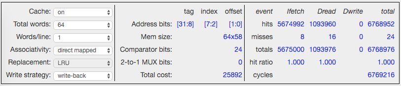
The control panel is organized as three sections: left-to-right
they are cache configuration, cache details, and cache statistics.
There are six cache controls, all of which can be used while
the simulator is running, so you can change the cache parameters
on-the-fly. Changes to the controls will reset the statistics.
Cache: turns the cache simulation on and off.
Total words: The total number of 32-bit data words
in the cache. To test different cache architectures, typically this
control remains fixed, while changing the other parameters to
determine how these data words are organized into sets of cache lines.
Words/line: The number of data words in each
cache line, aka the block size of the cache. The total number of
cache lines in the cache is Total words divided by Words/line.
Associativity: The number of "ways" in a set-associative
cache. "Direct mapped" refers to a 1-way cache. The cache lines are
apportioned equally between the ways. In a fully-associative cache,
the number of ways is chosen so that each way has exactly one cache
line.
Replacement: Determines the strategy used to
choose which way is updated when a collision causes a cache miss.
Not applicable for direct-mapped caches. LRU = least-recently used,
FIFO = first-in, first-out (sometimes referred to as
least-recently replaced), Random = choice is made
randomly, Cycle = choose the first way for first
replacement, the second way for second replacement, and so on in a
round-robin fashion.
Write strategy: Determines how to compute the cycle cost
of rewriting dirty cache lines to memory. Write-back = cost is
incurred once when the cache line is replaced. Write-through =
cost is incurred on each write to the cache line.
The following cache details are provided:
Address bits: shows how the 32 address bits from the
Beta are used when accessing the cache. The number of offset bits (minimum
of two) is determined by the words/line. The number of index bits is
determined by the number of cache lines per way. The remaining address
bits become part of the tag to be compared with the tag field of the
selected cache line.
Mem size: nways*(nlines*bits/line).
nways is determined by the associativity. nlines is determined
by the number of cache lines per way. The bits/line includes the
valid bit, dirty bit, tag field, and data bits (words/line * 32).
Comparator bits: the number of bitwise comparisons needed
to match the tag field, determined by the number of ways times the number
of bits in the tag field.
2-to-1 MUX bits: the number of 2-to-1 multiplexors needed
to select the appropriate data word to return to the CPU if the number
of words/line is greater than 1. This requires a tree of 32-bit 2-to-1 muxes:
the tree has depth 1 when words/line = 2, depth 2 when words/line = 4, and
so on. The total number of 2-to-1 muxes needed is 32*(words/line - 1).
Total cost: an estimate (good for relative comparisons)
of the total hardware cost including memory address logic, the memory data
array, the memory sense amps, the tag comparators, and the MUX logic.
All quantities are weighted by a rough estimate of their size in square
microns.
The following cache statistics are computed; the table is updated
while the simulation is running. Ifetch = instruction fetches,
Dread = read data loads generated by LD/LDR instructions, Dwrite =
write data stores generated by the ST instruction.
hits: Count of memory accesses that resulted in a
cache hit.
misses: Count of memory accesses that result in a
cache miss.
totals: Count of all memory accesses = hits + misses.
hit ratio: hits/totals.
cycles: Total number of cycles needed to satisfy
the memory requests to date. Each access costs one cycle to access
the cache. Memory reads generated by cache line refills and memory
writes generated by write-back or write-though of dirty cache
lines cost 10 cycles for the first word and 1 additional cycle
for each additional word on the cache line.

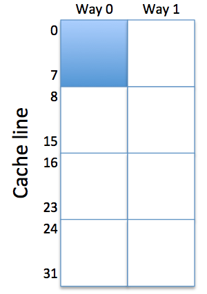 To analyze the Dfetch hit ratio, it's helpful to refer to
the figure on the right, which sketches the layout of a 2-way
set-associative cache with 64 total words. The instructions occupy
lines 0-7 in one of the ways (shown conceptually as the shaded area
of the cache). That leaves the other 7/8 of the cache for holding
array data.
The 64 elements of the array collide with themselves in a
cache with 32 lines.
To analyze the Dfetch hit ratio, it's helpful to refer to
the figure on the right, which sketches the layout of a 2-way
set-associative cache with 64 total words. The instructions occupy
lines 0-7 in one of the ways (shown conceptually as the shaded area
of the cache). That leaves the other 7/8 of the cache for holding
array data.
The 64 elements of the array collide with themselves in a
cache with 32 lines.